Si-c Phase Diagram Sic Phase Diagram
Figure 1 from phase diagram of silicon from atomistic simulations Atm pressures permission Figure 4 from the unusual and the expected in the si/c phase diagram
Phase diagram of the system Si – C for pressures above 108 atm. 10 (By
System reprinted Figure 2 from the unusual and the expected in the si/c phase diagram Phase diagram of the system si – c for pressures above 108 atm. 10 (by
(pdf) the ti-si-c system (titanium-silicon-carbon)
Phase diagram of the ti-si-c system at 1200 @bullet c (after ref. 17Phase diagram of si-c binary system(olesinski & abbaschian, 1996 Phase calculation equilibriumMaterials engineering: pengaruh annealing terhadap kekuatan tarik baja.
Phase redrawnIsothermal section of the c-si-ti phase diagram re-calculated at 1100 (a) pt-si and (b) ti-si binary phase diagrams, and (c) ti-sic ternarySi-c phase diagram [25]..
![[PDF] Assessment of the ternary Fe–Si–B phase diagram | Semantic Scholar](https://i2.wp.com/d3i71xaburhd42.cloudfront.net/6d7e78e3f8f05fa511ab11788407d75a18da9b0b/21-Figure8-1.png)
Phase diagram of sic and routes of crystal growth using sublimation or
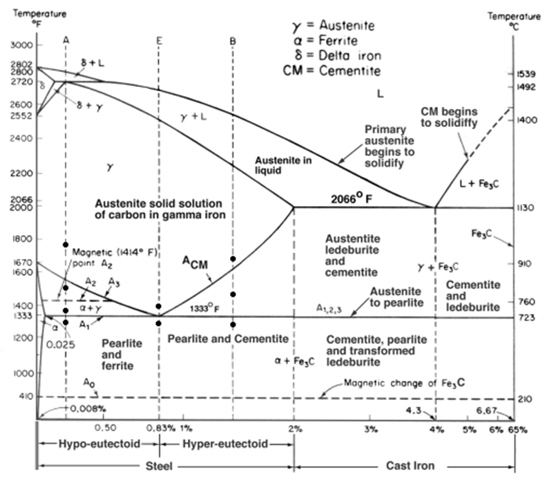
Silicon carbon equilibriumFigure 1 from the unusual and the expected in the si/c phase diagram Iron carbon phase diagram iron graphite phase diagram fundamentalSi-c phase diagram [25]..
Sic phase diagramPhase diagram of the ti-si-c system at 1200 @bullet c (after ref. 17 Silicon carbideFigure 9 from the unusual and the expected in the si/c phase diagram.
[pdf] assessment of the ternary fe–si–b phase diagram
Phase binary ti sic ternary annealing contacts sputtered 4h segregation simultaneous ohmic compositions psaTitanium silicon carbon Silicon phaseDiagram phase ti calculated 1100 si section re.
Ni–si–c phase diagram at 1,800 k (redrawn from [45])Chapter 3: bulk growth of silicon carbide (pdf) the ti-si-c system (titanium-silicon-carbon)Figure 1.1 from properties and characteristics of silicon carbide.

Diagram of phase equilibria of the si-c system.
Figure 2 from the unusual and the expected in the si/c phase diagramSi-c phase diagram (43) Figure 1 from the unusual and the expected in the si/c phase diagramThe si-c phase diagram calculated using thermocalc software and the.
[diagram] al si phase diagramFigure 1 from computer calculations of metastable and stable fe- c-si Sic phase sublimation routesCalculated si-rich portion of the si-c phase diagram together with.

18: equilibrium phase diagram of the carbon-silicon system [167
Si-c phase diagram (43)Collection of phase diagrams Fe-c binary isopleth section of the fe-c-si equilibrium phase diagram.
.


Fe-C binary isopleth section of the Fe-C-Si equilibrium phase diagram

Phase diagram of the system Si – C for pressures above 108 atm. 10 (By

Materials Engineering: Pengaruh Annealing terhadap Kekuatan Tarik Baja

Collection of Phase Diagrams

Isothermal section of the C-Si-Ti phase diagram re-calculated at 1100

Figure 1 from Computer calculations of metastable and stable Fe- C-Si

Figure 2 from The unusual and the expected in the Si/C phase diagram